
Bendix Air Brake System Schematic.pdf Brake Valve
The brake chamber itself consists of several interconnected components, including a pressure housing, diaphragm and pushrod. As the system exerts air pressure on the diaphragm, the pushrod on the.
Brake Chamber Diagram My Wiring DIagram
The brakes on your car are the same as air brakes, only the power source is different - watch the video. CDL IN-CAB Air Brake CHECKLIST: https://www.smartdri.

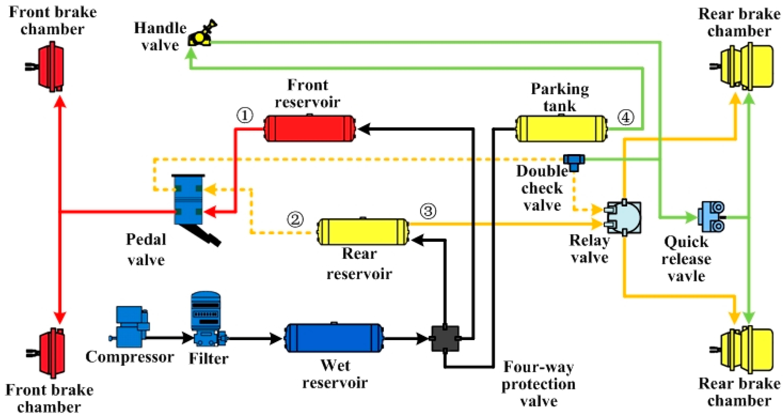
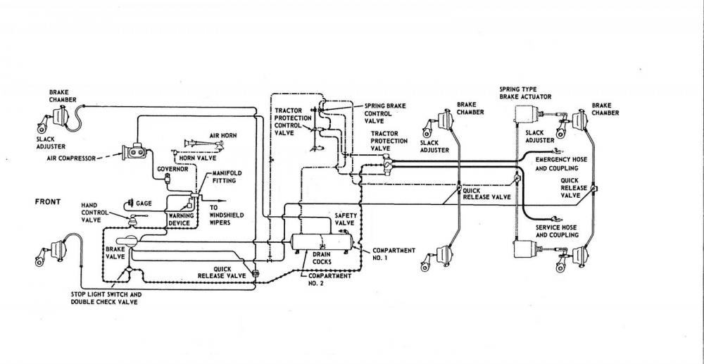
A general layout of the air brake system in trucks Download
Introduction Introduction The purpose of an air brake system on heavy duty vehicles is to convert air pressure to mechanical energy to activate the foundation brakes. Federal Motor Vehicle Safety Standard 121 dictates how this is to be done for over-the-road vehicles.

Air Brake Diagram Tractor Trailer Fleur Plumbing
An air brake line diagram is a visual representation of the components and connections in an air brake system. It helps truck drivers and mechanics understand how the system works and troubleshoot any issues. This article provides an overview of common air brake line diagrams and their key features.
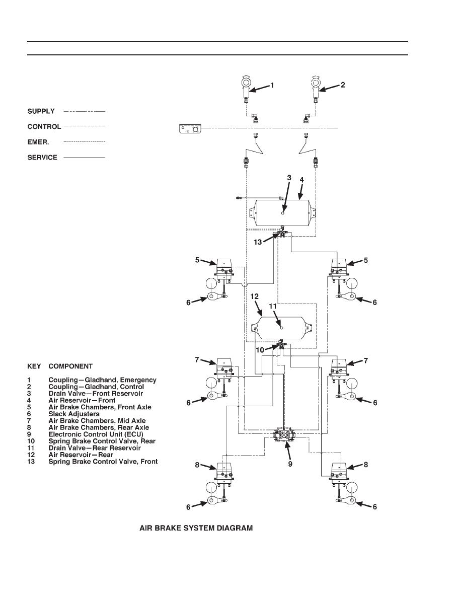
AIR BRAKE SYSTEM DIAGRAM
Air Braking System Diagram : Working principle: Difference between air brakes and hydraulic brakes : Probable causes and remedies of the air brake system Advantages of Air Braking System : Disadvantage Of Air Braking System : Applications of Air Braking System: Construction and working of Pneumatic ( Air) Brake System used in Automobile
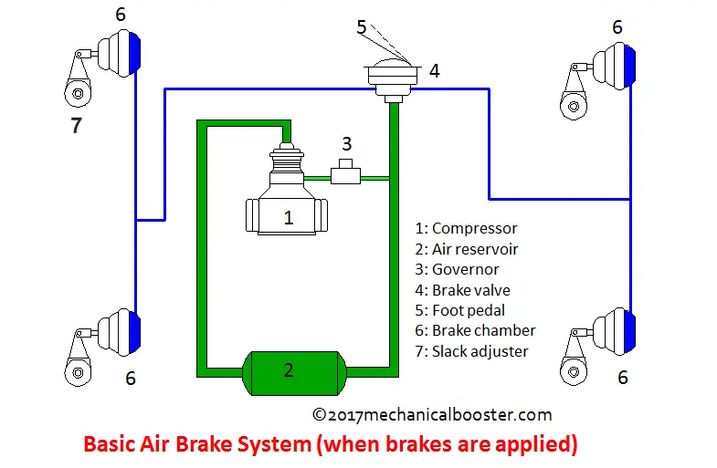
How Air Brake System Works in Automobile? Mechanical Booster
An air brake or, more formally, a compressed-air-brake system, is a type of friction brake for vehicles in which compressed air pressing on a piston is used to both release the parking/emergency brakes in order to move the vehicle, and also to apply pressure to the brake pads or brake shoes to slow and stop the vehicle.
Freightliner Air Brake System Diagram My Wiring DIagram
The functioning of Air Brakes System: A hand or foot-operated valve controls these diaphragms. When the driver applies brakes, the brake-valve controls the braking operation, directing the flow of air from a reservoir against diaphragms in the brake chambers. It directs the air form brake chambers to the atmosphere when the driver releases the.
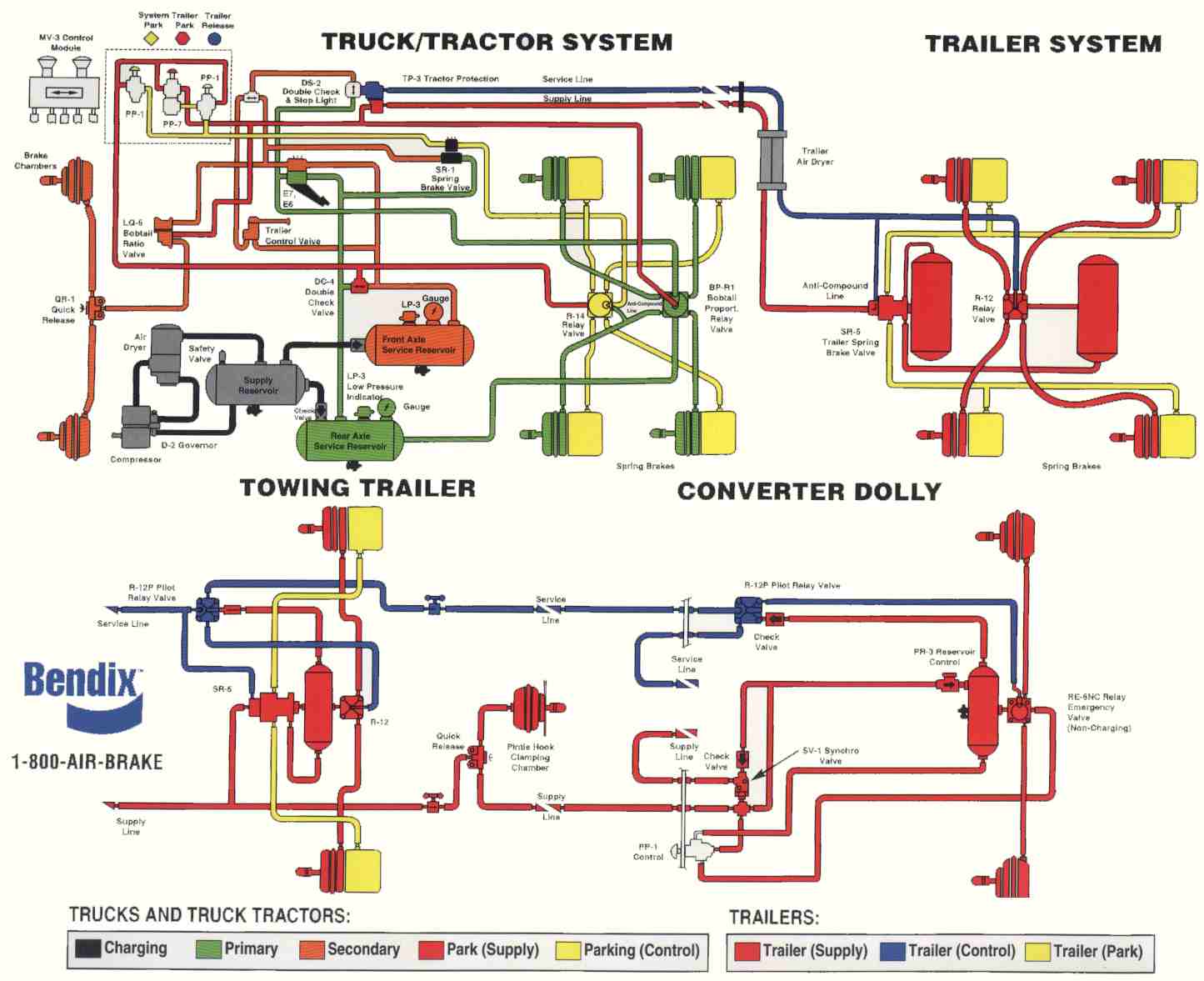
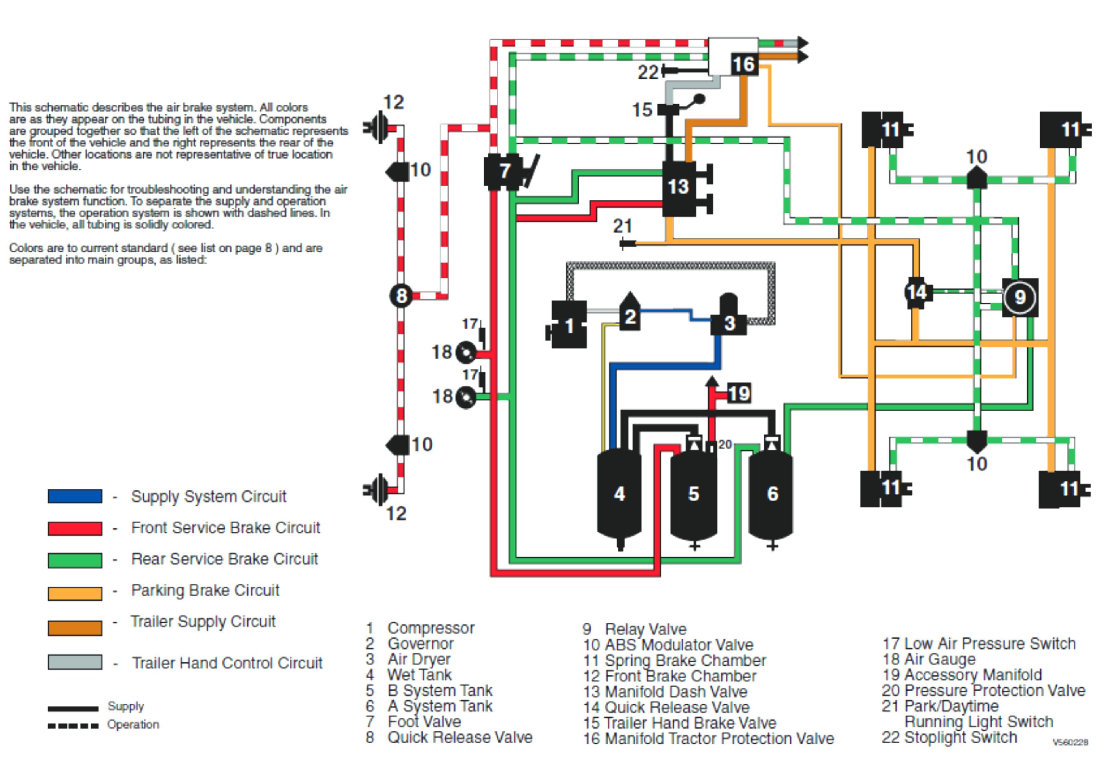
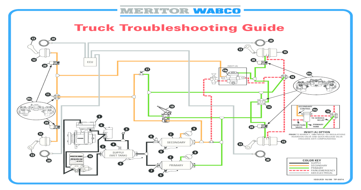
Bendix Air Brake Diagram
Diagram 1-1. Air brakes differ from hydraulic brakes. Most brakes are located at the wheels of a vehicle. The force you apply to the brake pedal is transmitted to the wheels to make the brakes operate. There are two main ways in which this force is transmitted - hydraulic brake systems and air brake systems.
B75 air controls Air Systems and Brakes
This video gives an introduction and brief look at air braking systems on heavy and commercial vehicles.You'll see from the animations that all systems have.
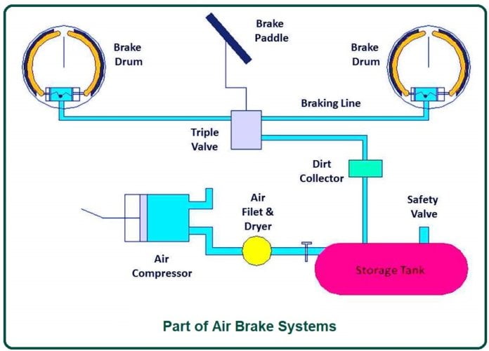
What Is Air Brake Systems? Working of Air Brake Systems Part of Air
The air brake system does this with an electric switch that works by air pressure. The switch turns on the brake lights when you put on the air brakes. 5.1.13 - Front Brake Limiting Valve. Some older vehicles (made before 1975) have a front brake limiting valve and a control in the cab. The control is usually marked "normal" and.
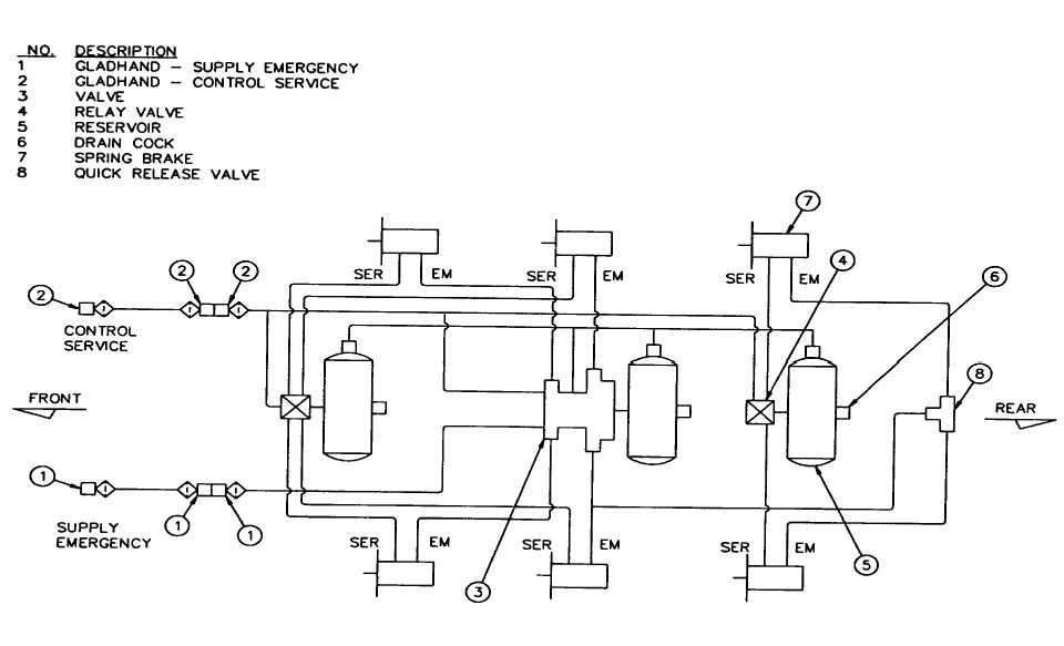
Figure 385. Trailer Air Brake System
Air brakes can be either drum brakes or disc brakes, or a combination of both. Air is pressurized by an engine-mounted compressor. The air compressor then pumps the air into the air storage tanks, which store the compressed air until it's needed. Air pressure is used to apply the service brakes and release the parking brake.
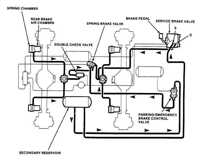
Figure 132. Rear Brake System Secondary Air Only
Air Brake Diagram George Westinghouse and Air-brake History Air is everywhere. Hydraulic fluid isn't. Trains, buses and tractor-trailers use air-brake systems so they don't have to rely on the hydraulic fluid in car braking systems, which can run out in the event of a leak.

the typical wiring diagram for an electric vehicle
An air brake system, also known as a compressed air brake system, functions as a friction brake in vehicles, employing compressed air on a piston to exert the necessary pressure on brake pads for vehicle cessation.
Air Brake System Diagram [PDF Document]
11K 1.2M views 7 years ago Educational Mechanics A more detailed look at the air braking system, in particular with this video at the air brake relay. Relays are fitted to an air braking.
Peterbilt Air Brake Diagram My Wiring DIagram
A pneumatic brake or compressed air brake system is the type of brake system in which the compressed fluid from the hydraulic system is replaced by compressed air to pressurize the piston of the master cylinder, which in turn stops to pressurize the brake pad or vehicle.
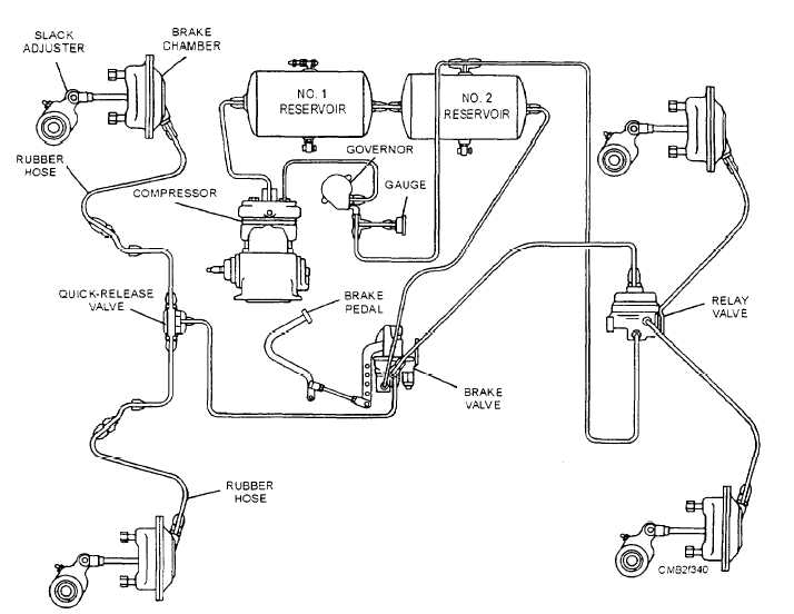
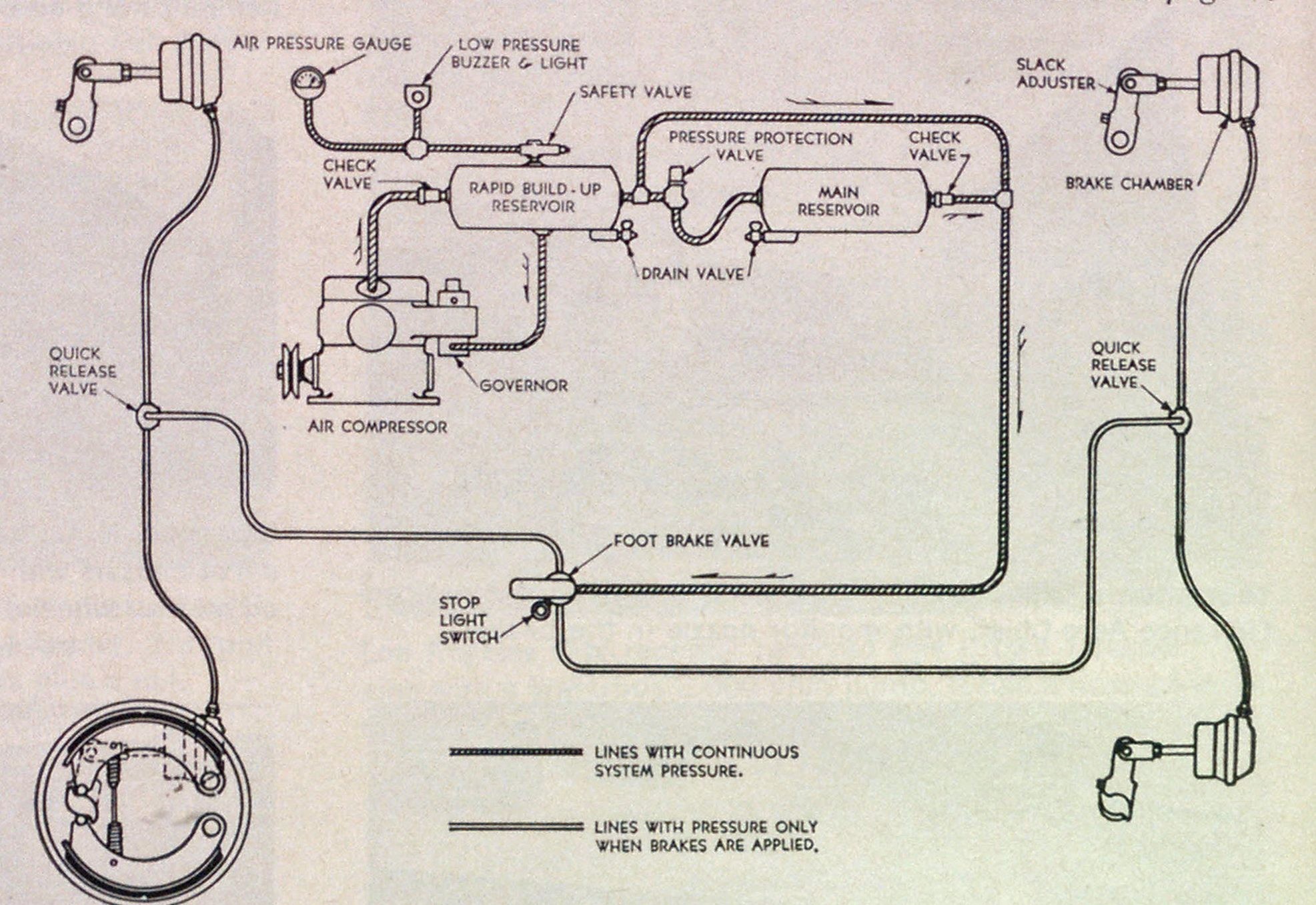
Figure 739.Typical air brake system
Air Brake System: Diagram, Parts, Working, & Application [PDF] Last Updated on: November 27, 2022 by Yousef In this article, you'll learn what is air brake system? Its diagram, parts, working, advantages, and applications all are explained with pictures. Also, you can download the PDF file at the end of this article. What is Air Brake System?